Sirius Hacking Part 1 - The Delta Row Compression
December 2022 (786 Words, 5 Minutes)
Foreword
This series of posts describes obstacles and findings while reverse engineering the firmware of the HP OfficeJet Pro 8710/8715 and is based on research done by JSOF. My goal with this project is to eventually be able to run Doom on the device.
Unpacking a firmware update
A firmware update of this printer has many different layers and JSOF did a great job explaining all of these layers in detail so I am not going too in depth. I was able to follow their blog posts and create a script which turns an update file (*.ful) into a flash image which can then be analyzed. The file I analyzed used a compression mode (in a single plane), also known as Method 3 or Delta Row Compression. This method was not explained by JSOF though, so I am going to do that in this post.
The update uses the special FWUPDATE language which uses PCL commands and Raster Graphics for data storage.
There are two types of data, Rows and Planes.
Rows are used for black and white pixels, Planes for colored pixels, and there are multiple of these in an update. This structure repeats itself until the End Raster command <esc>*rC.
Since the “pixels” are just bytes of the firmware, I am simply going to refer to them as data.
For simplicity’s sake, I will refer to Rows and Planes as Chunks since they are handled in pretty much the same way in the FWUPDATE language.
A Chunk is specified by the Transfer Raster command which has the following structure:
<esc>*b(Amount of data)(W/V).
This command can also specify the compression by having the type of compression followed by m before the amount of data.
| Value | 0 | 1 | 2 | 3 | 4 | 5 |
|---|---|---|---|---|---|---|
| Compression Type | Unencoded | Run-length encoding | TIFF | Delta row compression | Reserved | Adaptive compression |
If it doesn’t, the compression of the previous Chunk will be used. Here’s an example of five Chunks color-coded by their compression type and their data marked in green:

Delta Row Compression
Delta Row Compression basically only saves the differences between Chunks and applies them.
The data of a delta row compressed Chunk consists of a Command Byte and one to eight Replacement Bytes. The first five bits of the Command Byte specify the offset (0-30), and the last three bits specify the number of bytes to replace (1-8).
The replacement bytes are applied to the Seed Row with the respective offset.
Once any Chunk is processed (regardless of the compression type), it becomes the new Seed Row.
Here’s an example of three Delta Row compressed Chunks and a rundown on what happens each Chunk:
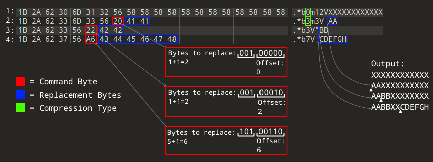 The small triangles represent the offset where we start replacing
- Output
12unencodedX’s as an exampleSeed Row. - Replace
2bytes (1 is specified but we have to add 1 every time since you can only represent 0-7 with three bits) at offset0of theSeed Row. This output is now the newSeed Row. - Replace
2bytes at offset2of the newSeed Row. This too becomes the newSeed Row. - Replace
6bytes at offset6of the newSeed Row. This too becomes the newSeed Row.
This (CommandByte)(ReplacementBytes) structure is repeated multiple times if the Chunk requires more than eight replacement bytes, the offset then specifies the offset from the last replaced byte.
Here’s an example of that as well:
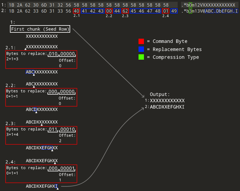 The small triangle above the command byte represents the offset where we start replacing. The ones below the command byte represent the offset from which the next offset is applied to (the last replaced byte)
Here’s the rundown:
- Output
12unencodedX’s as an exampleSeed Row. - Delta row compressed
Chunk:- Replace
3bytes at offset0of theSeed Row. Note that theSeed Rowdoesn’t change since we haven’t finished this chunk yet. - Replace
1byte at offset0, counting from the last replaced byte. - Replace
4bytes at offset2, counting from the last replaced byte. - Replace
1byte at offset1, counting from the last replaced byte.
- Replace
As you can see, the only notable difference is that we apply the replacements to the same Seed Row.
There’s also a way to have an offset bigger than 30 which I am going to skip since it’s not used in any firmware updates I have checked. Look at Raster Graphics 6-27 of the PCL 5 Color Technical Reference Manual for more information about this.
The update uses the latter format and using all of the info we have now, we can decompress the single chunk that uses this format with the same logic. Check out my unpacking script for an implementation of this.